
7. Feb 2021
Table of Contents
Introduction
This document describes the user registry settings that apply to ASIO4ALL revision 2 and derived individual versions thereof. It does not cover registry entries required by 3rd party standards, such as the registration as an ASIO driver and COM interface. All registry entries covered here are stored under the HKEY_CURRENT_USER registry hive and are therefore individual for each user account.
Structure Overview
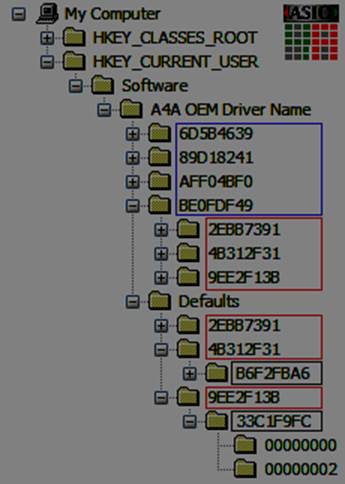
Registry sub keys are organized in the following hierarchy: Applications >> Audio Devices >> Device Interfaces >> Pins.
The illustration shows the registry location and basic structure of the user settings. The color marked eight-digit hex numbers are hash values created from strings using the following hash algorithm:
DWORD CreateHash (char inStr[])
{
  DWORD hash = 0;
  unsigned char x, y, z = 0;
  long idx = 0;
  while (x = (unsigned char) inStr[idx++])
  {
    y = (unsigned char) (hash & 0xFF);
    z = y - x;
    y^= x;
    hash = (hash & 0xFFFFFF00) + (DWORD) y;
    hash = (hash >> (z & 31)) | (hash << ((32 - z) & 31));
  }
  return (hash);
}
A check for hash collisions is performed and in case of a collision the resulting hash is incremented by one until no further collision is found. This method has been chosen because the structure is mostly static and the loss of a branch (i.e. worst case) will still not compromise the integrity of the application.
Hashes are created from the following string sources:
- The application path and executable name returned by GetModuleFileNameA (blue)
- The audio device PnP ID as maintained by the Windows Setup API (red)
- The device interface path name as per the SP_DEVICE_INTERFACE_DETAIL_DATA DevicePath member returned by the Windows Setup API (green)
Hex numbered sub keys that are notcolour marked directly correspond to the indexes of input-and output pins by which instances of each can be created.
The “Defaults” branch contains a complete set of application level settings which are used in place of per-application settings whenever there were no settings stored previously from within the respective application. Changes made using the desktop control panel (“Off-line settings”) are stored directly into the “Defaults” branch.
Registry keys
Flags
Type: DWORD
Applies to: Application / Device / Interface / Pin
This is a bit field that corresponds to the internal state and configuration settings for each item. Not all information is loaded from / written back to the registry, however. A number of bits serve internal housekeeping between sessions and should not be modified either. The following definitions apply:
#define A4A_FLAG_STATEMASK 0x00000060
GUI housekeeping, do not change!
#define A4A_FLAG_WATCHDOG_ENABLE 0x00000001 (application)
#define A4A_FLAG_SAFEMODE_ENABLE 0x00000002 (application)
Used to enable application level troubleshooting functionality. “Safemode” will start with audio disabled after a crash. The watchdog will try to prevent the audio thread from consuming 100% CPU time for extended periods by pausing and restarting audio periodically, thus keeping the system somewhat responsive. Either functionality is not fully tested and should not normally be enabled.
#define A4A_FLAG_NOINPUT 0x00002000 (application)
If your OEM build has a dedicated global “Disable Input” functionality (e.g. A check box by that name in the ASIO control panel) , it is controlled by this bit. Otherwise this setting is reserved.
#define A4A_FLAG_NOSHUTDOWN 0x00004000 (application)
This is used in conjunction with the “Safemode” feature above as a marker to indicate an unexpected shutdown (“crash”) of the application when last run.
#define A4A_FLAG_ADVANCED 0x00008000 (application)
If the GUI in your build offers distinct “Advanced” and “Simple” settings views, this bit indicates which one of these is active.
#define A4A_FLAG_HWBUFFER 0x00010000 (device / interface)
When set, enables the hardware buffer mode. This mode does not always work, meaning that results can be rather unpredictable. Use with caution!
#define A4A_FLAG_FORCESRC 0x00020000 (device)
When set, the driver will up / down sample whenever the application requests a sample rate of 44.1kHz and 48kHz is a supported sample rate of the WDM driver. This will also apply if the WDM driver supports 44.1kHz natively.
If this bit is not set, resampling will only be performed if necessary in order to support the 44.1kHz sample rate at all.
#define A4A_FLAG_FORCE16 0x00040000 (device)
When set, bit depth on the WDM/KS interface will be restricted to 16, even if the device claims support for greater bit depths. Otherwise the device will be run at the highest possible bit depth. This setting has no influence on the ASIO sample format, which will always be Int32Lsb.
#define A4A_FLAG_RTAUDIO 0x00080000 (device/interface)
#define A4A_FLAG_MEMBARRIER 0x00100000 (interface)
Marks WaveRT type device properties interface internally. Normally this information is not written back to the registry and if it is, it must not be changed!
#define A4A_FLAG_PULLMODE 0x00200000 (device)
(v2.9+) If set, ASIO4ALL will try to use pull mode on the WaveRT pins of this device. When not set, the (safer) polling (“push”) mode will always be used. (v2.8) This bit has no effect, pull mode will be used whenever possible.
#define A4A_FLAG_OFFSET_VALID 0x01000000 (pin)
#define A4A_FLAG_RELAX_NUMPLAYING 0x02000000 (device)
Internal housekeeping. Normally this information is not written back to the registry and if it is, it must not be changed!
#define A4A_FLAG_RUNNING 0x10000000 (device / interface / pin)
#define A4A_FLAG_ERROR 0x20000000 (device / interface / pin)
#define A4A_FLAG_AVAILABLE 0x40000000 (device / interface / pin)
Used internally to keep track of dynamic object states. Normally this information is not written back to the registry and if it is, it is of very little use and must not be changed!
#define A4A_FLAG_ENABLED 0x80000000 (device / interface / pin)
When set, the respective object is enabled in the current configuration. For a pin to actually become active, however, its parent interface must also be set to “enabled”. Likewise, for the interface to become active, the parent device needs to be set to enabled, too.
SampleRate
Type: DWORD
Applies to: Application
Unit: 1/s
This is the sample rate the driver will return to the host application ASIOgetSampleRate() call as the default sample rate.
BufferSize
Type: DWORD
Applies to: Device
Unit: Samples
The buffer size for the device to be returned by ASIOgetBufferSize () as the driver preferred buffer size. If more than one device is active, the device with the largest associated buffer size will have its respective value returned.
KernelBuffers
Type: DWORD
Applies to: Device
Unit: n/a
The number of buffers in the WDM/KS buffer queue. Can be either of: 2, 3 or 4.
LtcyIn
Type: DWORD
Applies to: Device
Unit: Samples
Additional input latency to return by ASIogetLatencies (). This parameter has no further impact on driver code execution and serves solely to support automatic latency compensation if performed by the host application.
LtcyOut
Type: DWORD
Applies to: Device
Unit: Samples
Additional output latency to return by ASIOgetLatencies (). This parameter has no further impact on driver code execution and serves solely to support automatic latency compensation if performed by the host application.
WndPos
Type: DWORD
Applies to: Application
Unit: X/Y coordinates
The previous on-screen location of the ASIO4ALL control panel window.
References
- ASIO SDK, Steinberg Media Technologies GmbH
- Windows Driver Kit, Microsoft, Corp.
- Win32 Software Development Kit, Microsoft, Corp.
- ASIO4ALL Instruction Manual, Michael Tippach
Copyright © 2003-2021, Michael Tippach
No warranty is given with respect to the accuracy of the information provided in this document. Unless agreed otherwise, product specifications are subject to change at any time and without notice.
All trademarks used herein are the fully acknowledged property of their respective owners and used for product identification purposes only.